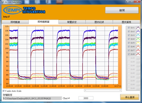
🚀 ZEL-100 Data LoMo: Your Universal Data Bridge
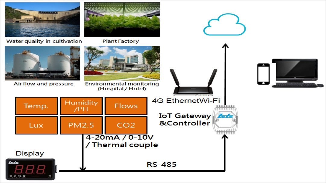
Say goodbye to fragmented data. Developed by TEMPOint, the ZEL-100 is a heavy-duty industrial monitoring platform designed for modern System Integration. With full Modbus RTU/TCP support, it seamlessly consolidates sensors, power meters, and high-precision instruments into one streamlined digital workflow.
⭐ The X-Factor: Our “Auto-Splitting Tech” ensures zero data loss and rock-solid stability even during massive long-term data collection.
📊 Industrial-Grade Stability Meets SQLite Power
SQLite Backend: Blazing-fast queries for millions of records
- ✅Smart File Auto-Splitting:
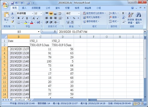
Tired of massive, crashing log files? ZEL-100 automatically segments data to guarantee integrity and system uptime during 24/7 monitoring. - ✅Instant Excel Reports:
Export your logs to Excel or CSV in seconds, complete with custom channel names and physical units for immediate analysis. - ✅Certification-Ready Logging:
Built-in operation logs and multi-level user permissions to meet strict industrial quality and traceability standards.
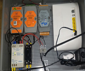
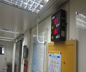
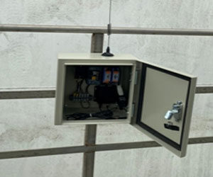
📍 Field-Proven Integration Expertise
We don’t just provide software; we solve your most complex connectivity headaches:
Seamlessly integrates with TSI Particle Counters and precision RH/T transmitters for automated compliance.
Connect Modbus Power Meters to build real-time energy dashboards and consumption analysis.
Pair with IO-200 modules for multi-channel TC/RTD logging—outperforming traditional paper recorders.
Utilize LoRa technology for long-distance data transmission, perfect for large-scale factory deployments.
| ZEL-100 System Specifications | |
|---|---|
| Core Database | Industrial SQLite (Optimized for Big Data) |
| Protocols | Modbus RTU / TCP, RS-485, Ethernet |
| Supported OS | Windows 11 / 10 / 7 (IPC Compatible) |
| Data Output | One-click Excel (.xlsx) / CSV export |
| Customization | Custom driver development & hardware SI available |
* Specifications are subject to change without prior notice.
Ready to Level Up Your Factory Data?
Stop struggling with manual logs. Get the professional edge with our ZEL-100 system.
📥 Download Technical Datasheet (PDF)
🔍 Technical Index:
Modbus Monitoring
Industrial Big Data
TEMPOint Solutions
Industrial IoT SI
TSI Particle Counter
Automated Excel Reports